This blog post is a collection of my personal notes on networking. For a long time, I had to jump between different notebooks to connect concepts; from core networking theory, to Linux internals, all the way up to Kubernetes and CNI. This post is my attempt to combine all those notes into a single, logical document.
We’ll follow a step-by-step path. We’ll start with fundamental network concepts, then see how those are implemented in Linux, which is the foundation for most modern virtual networking. Finally, we’ll see how Kubernetes builds on top of it all.
As a quick disclaimer, I’m writing this from the perspective of a software engineer, not a network engineer. This post is the guide I wish I’d had, and I’m sharing my learning journey in the hope that it’s as helpful to you as it has been to me.
Networking
Feel free to skip this section if you are familiar with Switch vs Router comparison at least.
Let’s start with fundamentals. Networking in general usually involves a lot of terminologies and acronyms, which makes it a bit challenging, at least for me, to understand when I need to check something. Therefore, understanding certain fundamental concepts might be helpful even in general tech literacy, even if you are not a networking engineer.
A “host” is almost any device connected to a network, like your phone, computer, server, or printer. So, ‘host’ is a widely used term, and it does not only mean ‘server’; it can be any device connected to a network. But what is a network? It is the underlying communication fabric, built from physical links, hardware, firmware, and software. It uses protocols to provide communication, or in other words, packet-delivery services, between these hosts. As an example, if you have multiple devices connected together with patch cables (like a router and your laptop), it creates a local area network, a LAN - in most simple setups, unless advanced isolation techniques are used.
Now you have a local network where multiple devices (laptops, phones, etc.) are connected to each other. The next question is, how do those hosts communicate? We need a way to say, “Okay ’laptop-xyz’, send this request to my printer ‘printer-abc’.” That’s where the MAC address comes into play. A MAC address is a unique hardware ID assigned to a machine, usually by its producer. For one host to send data to another on the same LAN, it must send that data to the receiver’s MAC address.
That’s good, but what happens if we change our laptop? The new laptop will have a new MAC address. If we only used MAC addresses, we would have to reconfigure everything to find the new one. As you can see, this would be a hassle and is an infeasible way to maintain a network, especially since devices are always joining and leaving.
This brings up a new problem. The MAC address solves the ‘where’ problem: where to send the packet on the local network. But it’s not good for the ‘who’ problem: who is the device I want to talk to, regardless of its specific hardware? This is why we have IP addresses (this is not the only reason of course). An IP address is a logical address assigned to a host. It’s the stable “who” we want to communicate with.
Also, please note that we don’t use IP addresses instead of MAC addresses; we use them together. Your application sends a packet to an IP address (the logical ‘who’). Then, your computer uses a special protocol to find the current MAC address (the physical ‘where’) associated with that IP. This two-part system gives flexible logical addressing (IPs) while still using the hardware MAC addresses to deliver the data on the local network to correct device.
But then, you may be wondering: how does a host find the MAC address for an IP address on its local network? This is done using the Address Resolution Protocol (ARP). For example, if host-a wants to send a packet to host-b (IP: 10.0.0.59), host-a initially has no idea what host-b’s MAC address is. It first broadcasts an ARP request to the entire network, basically asking, “Who has the IP address 10.0.0.59? Send me your MAC”. Every host on the network receives this broadcast, but only host-b recognizes its own IP and then sends an ARP reply directly back to host-a, saying, “I have 10.0.0.59, and here is my MAC address.” Once host-a learns host-b’s MAC address, it can send its packet destined to host-b’s MAC address.
Switch
Assume that our LAN has evolved and grown. Connecting every device directly to every other one becomes unscalable. The solution is a switch. Each device is connected to switch through ports located on the switch. Switch knows where to find those hosts based on the host’s connected port on switch. For example, if host-a and host-b are connected to port-1 and port-2 ports respectively, if host-a wants to send a packet to host-b, the switch knows that host-b is behind its port-2.
The most important feature of switch is that it allows communication within a network, using MAC addresses. This is quite important as we’ll need to refer to this switch feature in a lot of different places.
Router
The switch handles traffic within our network, but what happens when a device wants to communicate with a device on a different network, like a server on the internet? The switch, looking at the destination MAC address, will see that it’s not a local device and will send the data to the network’s exit point, the router.
Routers allow communication between networks. This is one of the crucial differences between switch and router. Traffic within a local network is usually handled by switch. But once the packet needs to reach wide area network (WAN), or in other words another network on the Internet, we need a router.
Router knows which networks that they can route by maintaining a routing table, allowing them to know where the corresponding IP address may be found in the WAN. When your router receives a data packet destined for Google, it doesn’t know Google’s MAC address but IP address. It consults its routing table and forwards the packet to the next router on the path, which repeats the process. This forwarding across many different networks is what allows you to reach any destination on the internet.
So, the key takeaways are that switching uses MAC addresses to move data within a single network, while routing uses IP addresses to move data between different networks.
OSI (L2, L3 and L4)
We are not going to dive into details of OSI layers; but it’s usually good to be familiar with certain mechanisms and terminologies related to OSI layers in general, as it helps us to understand more complex systems like container networking and Kubernetes.
Layer 2
Layer 2, the Data Link Layer, interacts between the Layer 3 (Network) and Layer 1 (Physical) layers. Its main responsibility is to take Layer 3 packets (like IP packets) and encapsulate them into frames for transmission over a physical medium. Also, it receives incoming signals from L1, reassembles them into frames, de-encapsulates them and passes the payload (the original L3 packet) up the stack.
L2 uses a special addressing scheme called MAC to manage the delivery. By using MAC, L2 identifies the receiver host, and sends the data to the correct host.
Your data travels across different hosts, for instance host to switch (which is a host) then another host to router, etc etc until it reaches its destination. This process is usually done by devices like network cards (NICs), or switch. As we saw previously, switch allows communication within a network. If devices are connected by a switch, the switch forwards packets between devices, to ensure host to host communication in a network.
The key takeaway for L2 is that it provides a mechanism for host-to-host (or host-to-router) delivery, which is the ability to move a frame from one host to another within the same broadcast domain (e.g., host-to-host on the same LAN, or host-to-router). And switch is mainly a L2 device; though you can find L3 switches on the market as well :).
Layer 3
Sending data between connected hosts is not our usual Internet experience. We need to send our packets to other networks to access services on those networks. L2 delivery only ensures host-to-host delivery which happens in a single network. However, usual packets need to go beyond that, across networks involving multiple host-to-host deliveries. This is where L3 comes into picture.
L3 ensures routing of packets and end to end delivery. It uses its own addressing scheme called IP addresses which, unlike physical MAC addresses, are not tied to specific hardware. A router, the key L3 device, makes this work. When a router receives a packet, it reads the destination IP address. It then consults its routing table (a set of rules) to decide where to forward that packet next.
The key takeaway is that L3 provides the end-to-end logic for packet delivery across multiple networks. It does this by making a series of hop-by-hop routing decisions using IP addresses.
In the following example, we have two networks connected to each other via Router:
 Network 1 (10.0.0.0/24)                              Network 2 (71.0.0.0/24)
┌──────────────────────┐                          ┌───────────────────────┐
│                      │            IF2:          │                       │
│                      │            MAC: DD       │                       │
│                      │            IP: 71.0.0.1  │                       │
│        HOST A        │       Router             │        HOST B         │
│    ┌─────────────┐   │      xxxxxxxxx           │    ┌─────────────┐    │
│    │MAC: AA      │   │     x         x          │    │MAC: BB      │    │
│    │             ┼───│──>  x         x────────> │    │             │    │
│    │IP: 10.0.0.50│   │     x         x          │    │IP: 71.0.0.59│    │
│    └─────────────┘   │      xxxxxxxxx           │    └─────────────┘    │
│                      │   IF1:                   │                       │
│                      │   MAC: CC                │                       │
│                      │   IP: 10.0.0.1           │                       │
└──────────────────────┘                          └───────────────────────┘
Host A (10.0.0.50) wants to send a packet to Host B (71.0.0.59). Host A checks its own local routing table. It compares the destination 71.0.0.59 to its own network (subnet, 10.0.0.0/24) and determines the destination is not its own network. So, it sends the packet to router which is usually defined as default gateway. In order to create the L2 frame, Host A needs the MAC address associated with 10.0.0.1. It uses ARP (Address Resolution Protocol), broadcasting a request: “Who has 10.0.0.1? The router’s IF1 interface replies: “I have 10.0.0.1, and my MAC is CC.” Host A now builds the packet and encapsulates it in an L2 frame to send to the router:
# Frame 1: Host A -> Router (on Network 1)

destination MAC: CC
source MAC: AA
--- (L3 Header) ---
destination IP: 71.0.0.59
source IP: 10.0.0.50
--- (Payload) ---
The router receives this frame on IF1 as the destination MAC matches, strips the L2 header and inspects the L3 header. Since the destination IP is 71.0.0.59, the router sends this packet to IF2 by creating again L2 header with the similar process (ARP request and then updating L2 header accordingly).
The router re-encapsulates the original, unchanged L3 packet into a new L2 frame, using its IF2 MAC (DD) as the source.
# Frame 2: Router -> Host B (on Network 2)

destination MAC: BB
source MAC: DD
--- (L3 Header) ---
destination IP: 71.0.0.59
source IP: 10.0.0.50
--- (Payload) ---
Finally, Host B receives this frame, strips the L2 header, and inspects the L3 header. It sees its own IP as the destination and accepts the packet, passing the payload up the stack.
Again, the key takeaway from this example is that the L3 header (IPs) remained constant for the entire end-to-end delivery, while the L2 header (MACs) was rebuilt at each hop.
Layer 4
We have delivered the packet to the correct host (HB), but when a packet reaches to its destination, that host might be running manny different programs, like a web server, an email server, etc. So, how do we know which program the packet is for? This is the job of Layer 4 (L4), the Transport Layer. This L4 header specifies a port number. For example, if HA wants to reach HB’s web server, it will set the destination port in the L4 header to 80. When HB receives the L3 packet and unwraps it, it looks at this L4 header, sees “port 80,” and knows to deliver the data to its web server, not its email server. This is how a single IP address can serve many different services at the same time.
Switching (L2 Domain)
We’ve covered the basics of a switch, but how does it actually manage traffic magically? This section explains the fundamental operations a switch performs.
As mentioned earlier, switches have multiple ports where devices (like PCs and servers) connect. To know where to send traffic, a switch builds and maintains a MAC address table. This table is crucial: it maps the MAC address of a connected device to the specific switch port it’s on. This table is what allows the switch to intelligently deliver frames to the correct destination.
When a frame arrives on any port, the switch follows a simple but powerful three-step logic: Learn, Flood, and Forward.
A Quick Note that the “Learn, Flood, and Forward” model is the most fundamental concept of L2 switching. Please be aware that this overview explains only the basics. Real-world switches perform several other important functions, such as filtering frames (dropping a frame if the destination is on the same port it came from) and aging out (removing) old entries from the MAC table to keep it up-to-date.
Learn
Switch maintains its MAC table with the port and updates it whenever a related frame passes through the switch.
For example, when Host A sends a frame to Host B, the initial MAC table state is empty. When the switch receives a traffic from Host A’s MAC address (let’s say AA) through port-a, switch learns and updates its MAC table to memorize port: port-a and MAC: AA.
Flood
Now, switch still does not know where to find Host B (which port should it use?). Therefore, the switch floods a unicast frame out all switch ports except the port it was received on. This is called flooding.
Once Host B receives the frame, it responds to the message through a port that it’s connected to, let’s say port-b. Now, switch receives this acknowledged response through port-b, and learns that port: port-b and MAC: BB.
Now, switch knows where to find Host B
FORWARD
The rest is a bit trivial actually. The switch knows ports and MAC addresses. It performs forwarding to deliver the frame. The Forward operation is the main job of the switch once its MAC table has information.
After the switch “learns” that Host B is on port-b, the “Flood” process is no longer needed to reach it. The next time Host A sends a frame to Host B, the switch receives it, looks at the Destination MAC address (BB), and checks its MAC table. It finds the entry for it port: port-b and MAC: BB and forwards the frame only out port-b. It drastically reduces network traffic and is the primary reason switches are much more efficient than old hubs.
Routing (L3 Domain)
Routing is the process of delivering data between different networks (inter-network communication) using a device called a router. This operation occurs at Layer 3 (L3) of the OSI model. If a host on one network (like your home LAN) needs to communicate with a host on a different network (like the internet), it requires a router to forward the packet.
Routing Table
Routers maintain a map of all the networks they know about, which is known as routing table. This table is essentially a set of rules, or routes, that tell the router which path to use to reach a specific network destination.
Example routing table contents, from https://en.wikipedia.org/wiki/Routing_table
| Network destination | Netmask | Gateway | Interface | Metric |
|---|---|---|---|---|
| 0.0.0.0 | 0.0.0.0 | 192.168.0.1 | 192.168.0.100 | 10 |
| 127.0.0.0 | 255.0.0.0 | 127.0.0.1 | 127.0.0.1 | 1 |
| 192.168.0.0 | 255.255.255.0 | 192.168.0.100 | 192.168.0.100 | 10 |
| 192.168.0.100 | 255.255.255.255 | 127.0.0.1 | 127.0.0.1 | 10 |
| 192.168.0.1 | 255.255.255.255 | 192.168.0.100 | 192.168.0.100 | 10 |
You might wonder how this table is created. Routes are typically added in three ways:
- Direct: the router automatically adds routes for networks it is physically connected to (e.g., the 192.168.0.0 entry).
- Static: a fixed route is manually added.
- Dynamic: routers peers each other (talks to each other) using routing protocols (like OSPF or BGP) to automatically learn about and share routes. This is essential in large, complex networks.
If you have checked Kubernetes networking related documents, you may realize that routing protocols, especially BGP, are usually mentioned as an option in the network fabric. BGP (Border Gateway Protocol) allows different networks to exchange routing information automatically. While it’s an advanced topic, the key idea is automated route discovery, and we will see BGP again when we discuss advanced networking patterns in Kubernetes. Also, if you are using managed services from cloud providers, as an end user, most of the time you do not need to work closely with BGP. This is because most cloud providers use an abstraction called “overlay networks” which we will also briefly see in the Kubernetes networking section. These overlays run on top of the provider’s complex underlying network, which itself may use BGP heavily, but that complexity is hidden from you.
A key entry in many routing tables is the default gateway (shown as 0.0.0.0 in the example). This is the “catch-all” route. If the router doesn’t have a specific route for a destination, it sends the packet to the default gateway if its defined. So, the default gateway is optional. So, based on the routing table, the kernel forwards data to the route.
NAT
NAT is a process where a router modifies the source and/or destination IP addresses in a packet’s header on the fly as it passes through.
Publicly routable IP addresses (like the ones you get from your ISP) are a limited (due to the nature of unique IPv4 addresses) and costly resource. In a typical home or office, your devices (laptops, phones) use private IP addresses (e.g., 192.168.x.x, 10.x.x.x). These addresses are not routable on the public internet. Only your main router has a single public IP address.
Then you may ask, how can your private device access the internet? And just as importantly, if a web server sends a response, how does it get back to your specific private device, which it can’t see?
This is solved by two main types of NAT:
SNAT (source NAT)
SNAT is the process where source IP is changed. This is important because addresses in LAN are not reachable from WAN. Thus, even though they can send requests to internet, internet can’t respond to those hosts. So, SNAT is being used for outbound connections, like when your laptop browses a website.
The process begins when your laptop (private host, e.g., 192.168.0.100) sends a packet to a web server (e.g., 8.8.8.8). This packet, with its private source IP, hits your router. The router then performs SNAT by changing the packet’s Source IP from 192.168.0.100 to its own public IP (e.g., 123.45.67.89). Also, it records this translation in a state table. The web server receives the packet from the public IP and sends its response back to that same public address. When your router receives this response, it checks its state table, sees the traffic belongs to 192.168.0.100, and translates the Destination IP back to your private host before forwarding it.
DNAT (destination NAT)
This is used for inbound connections, often called port forwarding. Imagine you are hosting a web server on your private network at 192.168.0.200. Since someone on the internet can’t reach this private address, you configure a DNAT rule on your router. This rule tells the router, “Any traffic that arrives at my public IP (123.45.67.89) on a specific port (like port 80 for HTTP) should have its Destination IP changed to 192.168.0.200.” This rule forwards the external request to your internal, private server, allowing it to host services for the public internet.
This entire stateful process requires the router to remember which internal host initiated which external connection. This mechanism is called connection tracking (or conntrack in Linux).
The conntrack system maintains an in-memory table of all active connections.
For SNAT, this table maps the original [private_ip:port] to the [public_ip:port] it was translated to.
Because this table is stored in memory, it has a limited size. This limit (e.g., nf_conntrack_max in Linux) can be reached if you have too many simultaneous active connections. It can also be a problem with a high rate of short-lived connections, as entries are kept in the table for a short time even after the connection closes.
If this table fills up, the router will start dropping new connections.
Linux Networking (Single Host)
This section covers the common Linux networking “toolbox” required to understand before jumping into Kubernetes networking. We’ll use standard Linux tools to build a complete, virtualized network inside a single host. The concepts we explore network namespaces, veth and virtual bridges that are the building blocks used by container runtimes and CNI. A grasp of these operations and concepts is key to understanding how container networking operates at scale.
If you are already comfortable with container networking, feel free to skip ahead.
Isolation (network namespaces)
As explained in Layer 2 section, a host uses network interfaces (NICs) for network communication. These interfaces can be physical (like the actual hardware on your laptop) or virtual, which we will discuss soon.
When you start your Linux machine, the kernel runs a single, default networking stack for you to manage all networking processes. This “root” stack is for everything running on the Linux machine. If you need to isolate this stack, you should use network namespaces.
Like other Linux namespaces, network namespaces isolate the networking stack. This allows us to spin up multiple containers on the same host while managing their networking stack differently, giving each one its own isolated network devices, firewall rules, ports, and route tables.
This isolation is very strong. When a network namespace is created, it comes with only a single, private loopback device (lo). It has no other interfaces, no routes, and no way to communicate with the host or the outside world. The rest of the configuration must be set by hand. To make this isolated “box” useful, we must provide it with a network connection. The most common method, and the one that powers container networking, is to use a virtual ethernet (veth) pair, which acts like a virtual patch cable.
The main tool we will use throughout this section is the ip command. The following is a quick demonstration of ip tool in Linux to manage network namespaces
For a more detailed reference, the
ipcommand suite is vast. RedHat provides a useful cheatsheet: https://access.redhat.com/sites/default/files/attachments/rh_ip_command_cheatsheet_1214_jcs_print.pdf.
| |
Let’s run a quick demo to see this isolation in action. We’ll create a namespace called “container0” and run a shell inside it:
| |
Network Device abstraction (ip link)
If you have come across ip commands before (or check the cheat sheet above), you may realize that ip link is widely used. This utility provides a great configuration layer for our isolated environment, by providing network device configuration.
In the last section, we used the ip netns command to manage the namespace itself.
Now, we’ll use ip link to manage the network devices (or interfaces) inside the namespace.
You’ll often hear these called network interfaces, link devices, or just links. These terms all refer to the same basic concept of a kernel object that can send or receive packets. They can have technical differences, but usually they refer to the similar functionality; sending and receiving data.
| |
Now, let’s use ip link show to see what network devices exist inside container0:
| |
As you can see, the namespace isn’t empty; it starts with a single device: lo, the loopback interface. This virtual device allows a host (or in this case, a namespace) to send network packets to itself.
If you examine this output, you’ll see the loopback device’s current state is DOWN. This means the device is not “up” or ready to function. But, what is the meaning of all of this? Why would you even care? Let’s try something simple, like pinging the loopback IP address 127.0.0.1:
| |
It fails. We get “Network is unreachable” because even though the lo device exists, it’s turned off, and the kernel can’t use it. Let’s fix this by using the ip link set command to bring the device “up”:
| |
It works. We have just configured our first network device. This lo interface is essential, but it only lets the namespace talk to itself. To talk to other namespaces or the outside world, we need to add new devices.
The cable (veth pairs)
Virtual Ethernet, or veth, does what we are looking for: it connects our namespace to another namespace.
In our above example, let’s assume we want to allow communication between container0 and container1. What can we do?
Remember the concepts mentioned in Networking section.
The simplest way to connect hosts was connecting them together with patch cable.
However, we now operate in the virtualized world. How could we make it? In the virtualized world, veth achieves this for us.
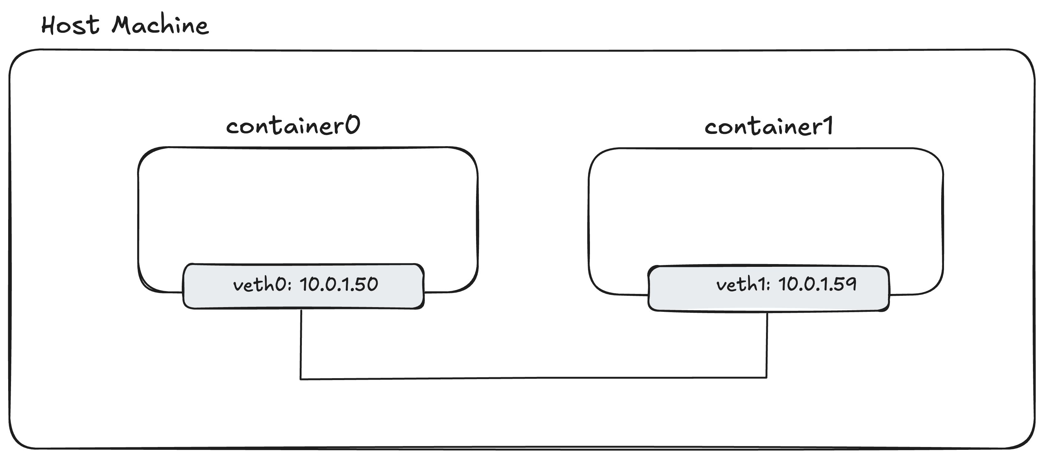
A virtual ethernet device, or veth for short, is a link device that is created as a pair, just like a patch cable. When a packet is transmitted on one end of veth, it is received from the other end. Thanks to this feature, we use a veth pair to connect container0 and container1 directly.
+------------------------------------------------+
|                                                |
|       container0              container1       |
|    +--------------+        +--------------+    |
|    |              |        |              |    |
|    |              |        |              |    |
|    |              |        |              |    |
|    +------+-------+        +------+-------+    |
|           ^                       ^            |
|           |                       |            |
|           |         veth          |            |
|           +-----------------------+            |
|                                                |
+------------------------------------------------+
The above diagram is what we want to achieve, so that we can ping container0 to container1.
| |
The command may look ugly, but if we read it as:
<ip link add veth0> <type veth> <peer name veth1>
It makes it a bit clearer to understand. It means we want to add a link device called veth0, whose type is veth. Since it’s going to be a veth, we need to give a name to its peer, or in other words, its other end.
Where should we run this command? Within the container0 or container1 namespaces, or on the host? Well, we usually create the veth pair in the parent namespace (the host, in our case) and then move each end into its corresponding namespace.
Now, let’s list what link devices we have in the host network namespace:
| |
As you can see, the veth pair is there, and both devices are state DOWN
Now, we’ll move one end into container0 and the other into container1:
| |
The IPs for network devices are visible in
ip addr showoutput. If you checkinetfield, its the IPv4 address, andinet6corresponds to IPv6 address.
Okay, now both containers are connected. Perfect, can we now ping the container1 from container0? Well, which address should we use? There is no IP address for the containers at the moment. What should get an IP address; namespace, the veth or something else? How can we assign an IP address?
Well, based on our discussion in the Networking section, we assumed hosts (devices) have IP addresses. So, we assign IP to network interfaces to allow communication through IP.
In our case, the “device” is the veth pair.
Since veth is a link device (a network interface), we can assign an IP to it and ping that IP.
Assigning IPs can be done via the ip command.
| |
This command assigns 10.0.1.50/24 to veth0 and 10.0.1.59/24 to veth1.
Since both of these IPs are in the same 10.0.1.0/24 subnet, the kernel will know they can reach each other directly over the veth “cable” through L2 network, without routing.
By calling ip link set dev veth0 up, we are setting the link (device, network interface) up, or ready to function.
Let’s check the IP addresses:
| |
Based on inet output, we can see that veth devices have IP addresses as we defined above.
Now, we should test if container0 can reach container1 by simply pinging IP addresses within the container network namespaces:
| |
It works. We have successfully created our first virtual network by connecting two isolated namespaces with a veth pair.
The Virtual Switch (bridge)
Having two containers and managing a direct connection between them is not a big deal. We just need to perform a couple of commands, and the two isolated network namespaces are ready to communicate.
However, think about scaling this system. If you have many containers, connecting them to each other directly will not scale. Does this issue sound familiar? Remember one of the benefits of switches. In the physical world, switches solve this exact problem. Instead of connecting hosts directly to each other, we connect all hosts to a central switch, which then handles communication between them.
A similar solution exists in the virtualized environment, and in Linux, it’s called a bridge.
A Linux bridge is a Layer 2 device that behaves exactly like a virtual switch. It builds a MAC address table and forwards frames between the devices connected to it. Because it’s L2, it does not know about IP addresses or routes.
From the host’s point of view, the bridge is just another network device (a link). From the containers’ point of view, it’s the “switch” they are all plugged into.
Our old setup was a direct veth “patch cable” between two containers:
Our new setup will look like this, with a central br0 bridge:
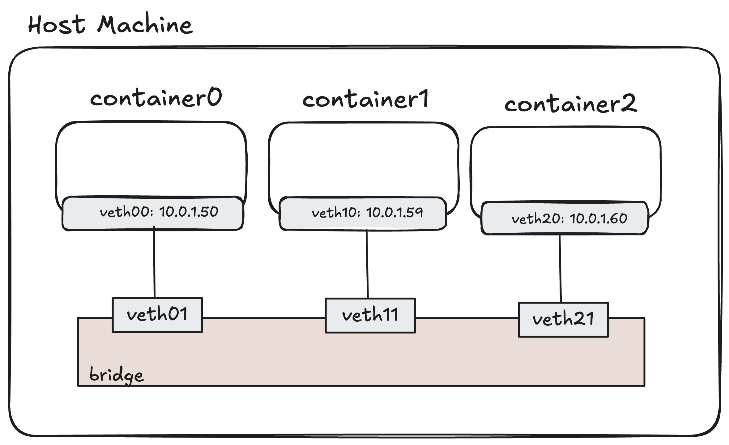
In this setup, introducing a new container or removing a new container (network namespaces) become quite easy. We just need to perform operations that we explained above. But instead of connecting veth pairs to host network, we connect one end of veth pair to bridge, and the another to container itself.
To set this up, we’ll create a br0 bridge device in the host namespace. Then, for each container, we’ll create a veth pair. One end will go inside the container namespace (and get the IP address), while the other end will be “plugged into” the bridge as a port.
Let’s build this. First, we need to create the bridge device. We’ll use the ip command again.
| |
That’s it. We now have a virtual switch that is on, but has nothing plugged into it. Now, let’s clean up our old setup and connect our containers to this new bridge.
Maybe you may want to try it yourself, by following the commands in the previous section.
| |
Now the setup is complete. We expect the similar behaviour, where containers can ping each other.
| |
It works! You may wonder the purpose of all hassle by setting up the bridge.
Since bridges work like virtual switches, adding a new container to this setup becomes easier than before.
We just need to add veth pairs, connect one end of the pair to container and another end to the bridge, assign IP address and set everything UP. Now the new container also can communicate with other containers, so we do not need to update every veth pair in other containers.
We have now built a scalable, single-host virtual network, which is the foundation of how Kubernetes and CNI work.
L3 Gateway
Our containers can communicate with each other. That’s perfect for offline environments. But most of the time, we also expect containers to reach other networks, especially the Internet.
Let’s check whether the containers can communicate with the Internet.
| |
Even though containers can ping each other, they cannot communicate with the Internet.
Remember, in the previous sections, we explained how packet delivery happens: L2 ensures host-to-host (or host-to-router) delivery, while L3 ensures end-to-end delivery. What are we missing here?
The simple answer is that the container network namespaces do not know any path to reach 8.8.8.8. Therefore, they cannot deliver the ping request (ICMP packets). We need to add a ‘route’ to instruct our system to find the path. In our host machine, we are able to ping the Internet. It seems the host namespace contains a route allowing it to access the internet, and this route does not exist in the containers.
In our host machine, we are able to ping the Internet. It seems the host namespace contains a route allowing it to access the internet, and this route does not exist in the containers.
To find out the reasons, we should look at how we reach the Internet from the host:
| |
ip route get <address> command allows us to check which route the host takes while reaching <address>.
In our case, we reach 8.8.8.8 via the eth0 device. If you list all routes, you’ll see why:
| |
As we mentioned in Routing Table section, the first entry is the default gateway, which is used if no other rule is matched. By using this rule, we are able to ping the Internet. We need to add a similar route inside the container namespaces.
Let’s first check the full routing table inside container0:
| |
This confirms our suspicion. The only rule it knows is the “direct” route for its local subnet. When we ask it to find 8.8.8.8, it doesn’t match this rule, and there’s no “default” to fall back on.
So, how do we give the containers a default route? We need to give them a gateway (a router) that they can send all non-local traffic to. The perfect candidate for this gateway is our own br0 bridge.
You might ask, why the bridge? In our last example, br0 was just a simple L2 switch and didn’t have an IP at all.
This is the key difference: to act as an L3 gateway, a device should have an IP address.
A fundamental rule of IP networking is that a host’s gateway must be on the same local subnet. This is so the container (e.g., 10.0.1.50) can use ARP to find the gateway’s MAC address.
Therefore, we will turn our L2 switch into an L3 gateway by assigning it an IP address on the containers’ subnet, 10.0.1.0/24.
If the bridge were only acting as a simple L2 switch for a network that didn’t need to talk to the outside world, it wouldn’t need an IP.
We’ll use 10.0.1.1 as the gateway IP. This will be the “internal” IP of our router, reachable by both containers.
It is not mandatory but convention to give
a.b.c.1IP addresses to the Gateway.
| |
Now, lets also instruct container network stack to route any non-local packets to bridge IP.
| |
Now container know that any traffic not destined for 10.0.1.0/24 should be sent to the gateway at 10.0.1.1. Let’s test the connection:
| |
It still fails! Why?
This may be confusing, since our containers can talk to each other.
That’s because the traffic between namespaces is a Layer 2 (switching) operation. The br0 bridge acts like a physical switch, and the packets never leave the bridge to be routed. The host’s main L3 (IP) routing engine isn’t involved.
If you remember the switching operations (learn, flood, forward) in Switching section, you may remember that Switch actually knows which MAC addresses are connected to which ports.
This operation only applies to within network traffic as we explained in the first section.
However, ping 8.8.8.8 is a Layer 3 (routing) operation. The container sends the packet to its gateway (the br0 interface), meaning that we need to reach another network. As you remember, this requires routing as we need to move data between networks.
The host’s kernel receives this packet on br0 and, after checking its own route table, sees it must send it out a different interface (like eth0).
This act of receiving a packet on one interface and forwarding it to another is called L3 forwarding (or IP forwarding). By default, the Linux kernel disables this for security, where the kernel will simply drop packets that are not destined for its own IP addresses, refusing to act as a router between interfaces.
We must explicitly enable this by setting net.ipv4.ip_forward=1, which tells the kernel to forward packets between network interfaces.
That’s the first problem.
The second problem is NAT. The packet from container0 has a source IP of 10.0.1.50.
The internet doesn’t know how to send a reply to this private IP.
We must use iptables to “masquerade” the packet, rewriting its source IP to the host’s public IP (192.168.215.2).
Okay, you might think, what is iptables since we never mentioned it yet.
In simple words, iptables is a program that allows us to set rules for packets.
You can create iptables rules to filter, modify, or redirect packets.
It’s a powerful tool for building firewalls, and it’s also commonly used to implement NAT because its rules allow “mangling” (updating) the packet itself.
iptablesis a complex tool, and while it’s now being replaced by modern alternatives, its concepts are still fundamental to Kubernetes networking.
So, let’s update our host machine to enable IP forwarding:
| |
And, we need to add an iptables NAT rule.
This command is a bit long, but what it means is that “For any packet in the nat table, in the POSTROUTING (after-routing) chain, if it’s from our container subnet (-s 10.0.1.0/24)
and going out the -o eth0 interface, then -j MASQUERADE (change its source IP to eth0’s IP).”
| |
Now, all the pieces are in place. Let’s try one last time:
| |
Finally it works! We have successfully connected our isolated containers to the internet.
Kubernetes Networking & CNI
It’s been a long journey but here we are, Kubernetes networking. We are not going to dive into too much details about technical requirements of the Kubernetes networking. Kubernetes’ official documentation clearly explains the problems that we need to address, as follows:
- Highly-coupled container-to-container communications: this is solved by Pods and
localhostcommunications.- Pod-to-Pod communications: this is the primary focus of this document.
- Pod-to-Service communications: this is covered by Services.
- External-to-Service communications: this is also covered by Services.”
https://kubernetes.io/docs/concepts/cluster-administration/networking/
Motivation and Automation of Linux networking
In the last section, we built a single-host virtual network. We manually created namespaces, veth pairs, a bridge, and configured routing. The goal of Kubernetes networking is to automate this entire process at a massive, multi-node scale.
One of the core principle of Kubernetes networking is a unique IP per pod model. To understand why this is so important, imagine scaling a web application. You need three replicas, and they all want to listen on port 80. On a single machine, this is impossible, as only one process can bind to a port at a time. This creates a problem of coordinating ports for all your microservices.
Kubernetes solves this by giving every Pod its own isolated network namespace and a unique IP address. Because each Pod has its own network stack (through a dedicated network namespace), there are no port conflicts. Your three replicas can all bind to port 80, each on its own IP (e.g., 10.244.1.10:80, 10.244.2.20:80, 10.244.3.30:80). This simplifies application development and management, as you no longer need to manage port assignments.
Note: A Pod can also use
hostNetwork: true, which skips this process, doesn’t get its own IP, and just shares the node’s network, but this is for special workloads.
To make this model work, Kubernetes requires an L3 network. This means all Pod IPs must be reachable from all other Pod IPs, no matter which node they are on. Therefore, this is quite important and technical aspect that we didn’t cover it yet.
The first problem Kubernetes networking solves is connectivity: “How do we give a Pod its own network namespace and a unique IP, and then make it reachable by other Pods?”.
Another problem is discovery of Pods. Pods are ephemeral; they can be destroyed and replaced at any time, getting a new IP.
This means you can’t rely on a Pod’s IP address. This is solved by a Kubernetes Service.
A Service provides a single, stable virtual IP and a DNS name (e.g., my-service.prod.svc.cluster.local).
There is an agent running on each node to manage host level networking and watches the Kubernetes API and updates rules on the host (using iptables, IPVS, or nftables) to map the Service IP to the real Pod IPs. Other tools like Cilium can also do this as kube-proxy replacement, by using eBPF.
We also have more problems, for instance reachability, which will be discussed in the next chapter
CNI (Container Networking Interface)
CNI is a specification that tells the container runtime to call a “plugin” (or program) to handle the network setup for containers.
It solves the problem of “giving a Pod its own network namespace and a unique IP, and then making it reachable by the cluster”. Therefore, we can say that CNI helps to create an isolated network for pod, to allocate the Pod IP, and make the IP reachable by the cluster.
Our demo in Part 2 where we manually created veth pairs, a bridge, and iptables rules is a good illustration of how one of the most common CNI plugins (the bridge plugin) works under the hood.
Other CNI plugins might solve this problem in completely different ways, such as using eBPF, IPVLAN, or different routing techniques.
We should indicate that CNI is not only for Kubernetes, it’s a generic specification for container networking. Kubernetes in this scenario is just an orchestrator or runtime, which triggers CNI plugins, to set up a network environment for the Pod.
CNI Plugin
According to CNI specification, “plugin is a program that applies a specified network configuration”. Roughly, the container runtime calls CNI plugin, meaning CNI program, to prepare the container networking. So, if we move the codes that we use in the demo into a bash script and make it executable, it can be good starting point for us to write our own first “plugin”.
Though i still do not understand the motivation behind ’executable’ plugins, instead of RPC based plugins like other Kubernetes out-tree interfaces (CRI or CSI).
The good part about CNI specification is that it allows chaining the plugins. Meaning that you can develop and use existing CNI plugins, and combine them to come up with your own container networking solutions. For example, you can use “ipam” plugin along with “bridge” plugin, so that “bridge” plugin can create the demo environment that we set and “ipam” plugin can manage the IP address assignment to those resources.
Since Kubernetes expects more than Pod connectivity, CNI Plugins are usually shipped with additional component(s).
- The binary is usually the one that we call the plugin. So, its main purpose is configuring the pod network interface, which is for “connectivity”.
- Daemon is managing the routing. So, its mainly for “reachability”
There are various ways to ensure “connectivity” and “reachability”, and we saw one possible solution for “connectivity”, in our bridge example.
“Reachability” though require more work. The CNI specification itself does not involve reachability; it covers the container networking (connectivity) and some runtime (e.g, Kubernetes) rules while calling CNI plugins. Therefore, reachability is a bit specific to Kubernetes networking requirements.
The purpose of the reachability is ensuring every Pod is accessible from every node. So, it’s a bit related to route lifecycle; thus, we should somehow announce the routes to each pod to each node. Therefore, Kubernetes CNI solutions ship with the ‘daemon’ running on each node to ensure that the network is configured in a way that all Pods are accessible across nodes.
How could we make it possible? As we mentioned in previous section, if nodes are in the same L2 network, we could utilize Switch + Routers. But the common ways to solve this are ‘Overlay Networks’ (e.g, VXLAN or IP-in-IP) or ‘Routing Protocols’ (BGP or OSPF).
There might be other hacky solutions as well; but these are the most common ones I faced.
How CNI Plugins Called
The CNI (Container Network Interface) specification defines how a container runtime, like Kubernetes, interacts with network plugins. This guide covers the fundamental operations and concepts you need to know. If you are looking for more details, please take a look at the actual specification, https://github.com/containernetworking/cni/blob/main/SPEC.md.
A runtime calls a CNI plugin by providing two key inputs: a JSON network configuration (via STDIN) and a set of environment variables.
Network Configuration File
The runtime finds network configurations by searching a dedicated directory, typically /etc/cni/net.d. Kubernetes, for example, monitors this directory periodically for configuration files.
This directory can be configured; therefore, in your cluster, it might be located somewhere else.
This JSON file contains settings for the runtime and for any plugins it needs to call, such as bridge or ipam.
Here is an example of a simple network configuration:
| |
When the runtime reads this file, it identifies the main plugin to run from the “type” field.
In this case, it’s bridge. The runtime will then look for an executable file named bridge in its plugin search path (usually /opt/cni/bin).
It is critical that network configuration files remain static while in use. CNI operations are not designed to handle configuration changes between an ADD and a DEL command.
For example, assume your configuration uses CIDR-A when a pod is created. If you modify the file to use CIDR-B before that pod is deleted, the CNI plugin will not know about the original CIDR-A. This will likely cause the plugin to fail when it tries to clean up the old network interfaces during the DEL operation.
CNI Operations
The JSON configuration defines what the network should look like, but it doesn’t specify what to do. The runtime tells the plugin which action to perform by setting environment variables.
The most important variable is CNI_COMMAND, which defines the operation:
ADD: Add container to network, or apply modificationsDEL: Remove container from network, or un-apply modificationsCHECK: Check container’s networking is as expectedSTATUS: Check plugin statusVERSION: probe plugin version supportGC: Clean up any stale resourcesReference CNI spec
Other variables provide the context for the command:
CNI_NETNS: A path to the network namespace (e.g,/var/run/netns/{ns})CNI_IFNAME: Interface name to create ‘inside’ the container.CNI_PATH: List of paths in the system to search CNI plugin executables.CNI_CONTAINERID: Container ID for the container.CNI_ARGS: Extra args provided by runtime.
Example: An ADD Operation
Let’s put this all together.
Imagine we want to add a container with ID c123 to the network namespace container0, using the configuration file /etc/cni/net.d/10-mynet.conflist (which contains our JSON example).
The runtime would execute a command similar to this:
| |
In this command, the runtime pipes the JSON configuration to the bridge plugin’s STDIN and sets the environment variables. The bridge plugin executes and reads the config.
If you remember our quick demo, this configuration instructs the bash commands we run to:
- Create
eth0interface in container (instead ofc0-veth) - The network namespace you need to operate is
container0, which means thatip netns exec <given_namespace> $operations
You may also see
CNI_NETNS_OVERRIDE. This variable is not part of the official CNI spec but is used by thelibcniGo package. It acts as a guard-rail to stop the plugin from modifying the wrong network namespace if the namespace path changes unexpectedly during the operation. This should ideally not happen with modern container runtimes, as they do not rely on process ID based paths for network namespaces.
Kubernetes and CNI
But how does Kubernetes use CNI? We mentioned that we may have multiple “plugins” available. We should somehow instruct Kubernetes to use correct plugins.
Kubernetes manages Pods with CRI (Container Runtime Interface), which is triggered by kubelet.
So, kubelet calls CRI via gRPC API, and your cluster can use various CRI implementations (RPC implementation).
While setting up a Pod, kubelet calls “rpc RunPodSandbox(RunPodSandboxRequest)”,
which in turn calls underlying CRI.
While CRI is setting up the Pod, it internally calls CNI to make sure that Pod’s network environment is ready.
That’s actually how Kubernetes calls CNI. It’s a bit of a chain of calls but to simply put: kubelet -> CRI -> CNI
For example, how container-d calls CNI in RunPodSandbox: https://github.com/containerd/containerd/blob/1c4457e00facac03ce1d75f7b6777a7a851e5c41/internal/cri/server/sandbox_run.go#L261-L263
CRI (Container Runtime Interface) calls CNI to set up the pod network, by following the above example. Then, based on CNI configurations and arguments, the CNI performs operations to set up the pod network.
Writing CNI Plugin in Go
The “bridge” demo we created is actually quite close to being a CNI plugin. We just need to make it aware of the CNI environment variables (like CNI_COMMAND) and
make it read from STDIN and write to STDOUT, as defined in the CNI specification.
However, if you’ve ever checked the official plugins, they are usually not shell scripts.
We need to handle JSON, error reporting, and complex networking operations, which is a better job for a language like Go.
This section will go through my notes on what I learned from the official “bridge” plugin while writing my own.
The source code for the CNI maintained “bridge” plugin: https://github.com/containernetworking/plugins/tree/v1.8.0/plugins/main/bridge
CNI maintainers provide official Go packages to handle the common boilerplate. This includes reading CNI environment variables, parsing the network configuration from STDIN, validating them, and formatting the result as JSON to STDOUT. Building all of this from scratch would be tedious.
The libcni package (https://pkg.go.dev/github.com/containernetworking/cni/libcni) and especially the skel package (https://pkg.go.dev/github.com/containernetworking/cni/pkg/skel) are designed to solve this.
The skel package provides a skeleton for a CNI plugin. It implements all the argument parsing and validation, like checking if all required environment variables are defined for a given CNI_COMMAND.
| |
As a plugin developer, you just register your functions for the Add, Check, and Del commands.
The skel package handles calling the right function and provides a struct containing all the parsed arguments and network configuration.
The rest is just implementing the networking logic based on the provided information.
Let’s skip the configuration parsing and dive into a Go-specific trick you’ll need.
Go Scheduler and the Problem
One thing I realized is that most CNI plugins use runtime.LockOSThread() before they change network namespaces.
This isn’t a function I use in my typical day-to-day work.
Understanding why this is necessary led me to learn much more about how Go’s scheduler works with OS threads.
The Go scheduler’s job is to run these N goroutines on M OS threads (this is called an M:N scheduler).
GOMAXPROCS limits the number of OS threads that can execute user-level Go code simultaneously. By default, this is set to the number of available CPU cores. Note that Go can create additional OS threads beyond this limit when threads block on system calls, but those blocked threads don’t count against the GOMAXPROCS limit. Only threads actively executing Go code are constrained by GOMAXPROCS.
The Go scheduler maintains multiple runqueues to manage goroutines efficiently. There is a global runqueue shared by all threads, and each thread has its own local runqueue. This design minimizes lock contention. When a thread needs work, it first checks its local queue, and if empty, it can steal work from other threads’ queues or check the global queue.
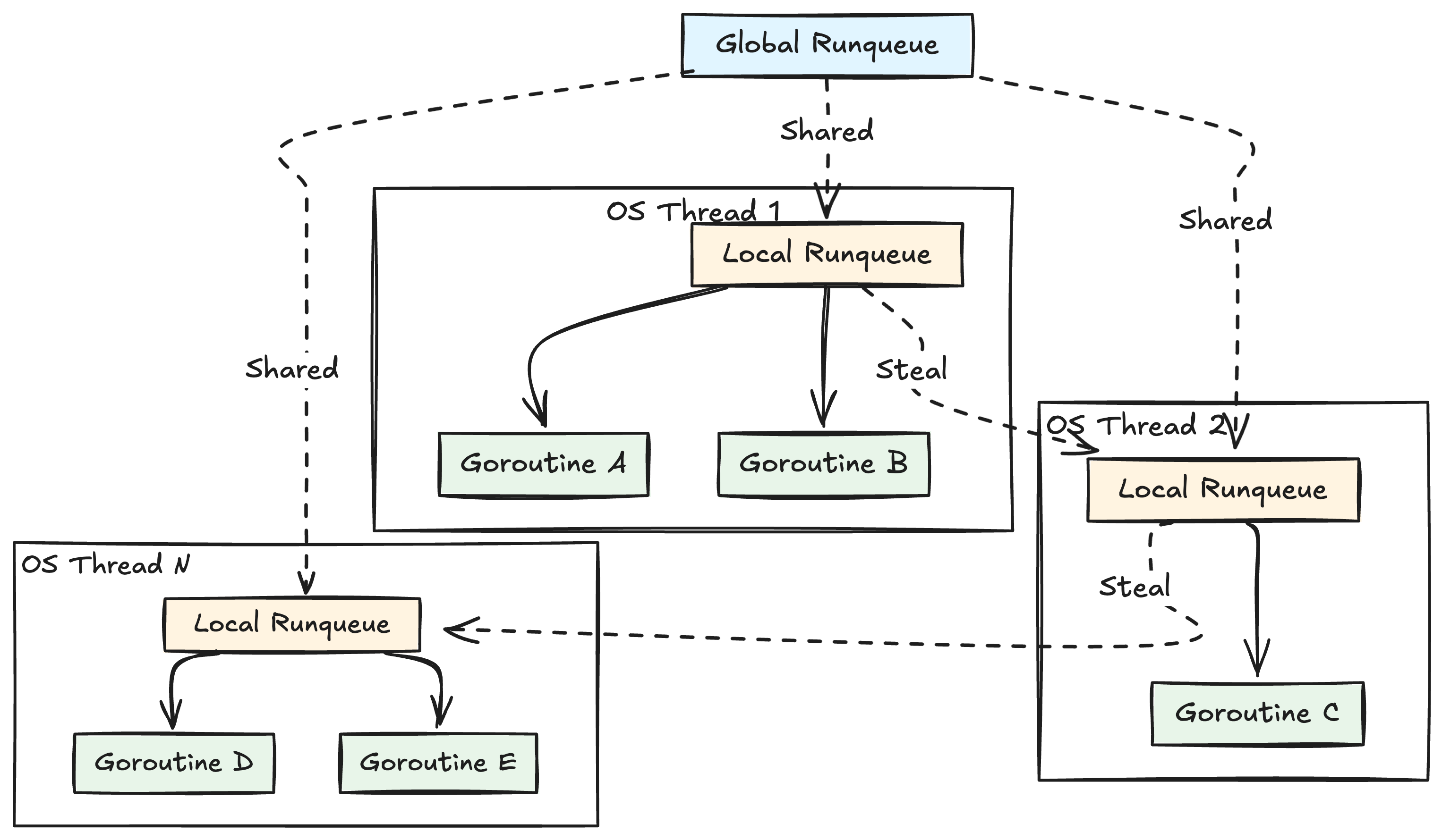
The Go scheduler uses asynchronous preemption. This means that if a goroutine runs for too long (e.g., more than 10ms), the scheduler can forcefully pause it and schedule it to run again later. This is great for fairness, as it prevents one CPU-heavy goroutine from starving all others.
For example, if you have a goroutine that blocks the CPU and not being able to voluntarily give up its control to CPU back (due to some maybe hardware flaw), then other goroutines in the OS thread’s runqueue needs to wait for this long running to finish.
This preemption has a critical side effect: a goroutine is not guaranteed to stay on the same OS thread. It might run on Thread 1, get preempted, and later resume its work on Thread 2. For most code, this doesn’t matter. But for a CNI plugin, it’s a huge problem.
Issues with Go and Network Namespaces
You might be wondering, “What does this have to do with CNI?”. The problem lies in how we change network namespaces.
When we create a network namespace for a pod, we need to run commands inside it.
We don’t use the ip netns exec command; instead, we use a Linux system call: setns(2) under the hood.
The setns(2) syscall is very specific: it changes the namespace of the calling thread, not the whole process. So, this Linux system call associates a thread with a namespace, not a process with a namespace.
In Go, this might be a bit problematic due to Go scheduler behavior.
Go scheduler can preempt the goroutine and move it to another OS thread, due to motivations explained in the previous section.
For example, assume that cmdAdd goroutine is running on OS Thread A (which is in the host netns).
The goroutine calls setns() to enter the pod’s netns, which changes OS Thread A’s state. Now, the thread is in the pod’s network namespace. Your goroutine continues, preparing to create the veth pair.
BAM! The Go scheduler preempts your goroutine because your time is up, the turn is for the next scheduled
goroutine. A moment later, the scheduler decides to resume your goroutine. It picks OS Thread B (which is still in the host netns) to run it.
Your goroutine, unaware it has been moved, continues where it left off. It tries to create the veth pair, but it’s now running on OS Thread B, so it incorrectly modifies the host network instead of the pod’s network. This is a subtle and dangerous bug :(.
goroutine -> OS Thread A (namespace: host)
                 |
                 | (preemption, goscheduler moves goroutine to the new thread)
                 v
             OS Thread B (namespace: somethingelse)
Solution: runtime.LockOSThread()
This is precisely what runtime.LockOSThread() solves.
When you call runtime.LockOSThread(), you are telling the Go scheduler: “Pin this current goroutine to the current OS thread”. It does not stop the scheduler. Your goroutine can still be preempted. But when the scheduler resumes it, it is forced to resume it on the exact same OS thread it was pinned to.
When we lock the thread, it also prevents the Go scheduler from running other goroutines on that thread.
This is useful if your goroutine modifies the thread’s namespace state (like network namespace operations). It ensures that no other goroutine that might also try to update thread state (like changing the network namespace) gets scheduled on that thread.
For example, when a goroutine calls runtime.LockOSThread(), it is now pinned to OS Thread A.
When this goroutine running on Thread A enters the pod network namespace and gets preempted, the scheduler will resume the goroutine on the same OS Thread A. In the meantime, no other goroutines will be scheduled on that thread.
This is why you see most of the namespace-switching logic in CNI plugins using a LockOSThread/UnlockOSThread block.
One final remark is that this thread lock is not inherited by new goroutines. If you spawn a new goroutine from your locked one, the new goroutine can run on any thread.
| |
Therefore, do not spawn a new goroutine from a locked one if the new goroutine is expected to run on the same thread.
LockOSThread() works like a taint. If you do not unlock the thread, the thread will not be used for scheduling other goroutines anymore.
When the locked goroutine exits without unlocking, the thread itself will be terminated.
So, do not forget to unlock the thread (unless you know what you are doing) to return it to the scheduler pool.
To obtain the current ns of the thread, you can simply use
/proc/${os.getPid()}/task/${unix.Gettid()}/ns/net
Bridge Plugin
The official Bridge plugin roughly performs the following operations:
| |
So, what we are doing is as follows:
- setup bridge
- setup veth pairs
- run IPAM plugin and configure veth and bridge to ensure they have IP
How does it create links (devices)? For that, it uses https://github.com/vishvananda/netlink package
which is an API to perform operations similar to ip link add by communicating with the kernel.
And this package is the Go binding of this kernel communication.
The Do method is quite powerful method, which is defined as follows:
| |
It is a powerful method that achieves what we are looking for. It locks the thread, runs our Go code in that thread to safely manipulate the thread, and takes the network namespace where the operation has started (like host).
So, Do ensures the user operation is safe by locking the goroutine to a specific OS thread,
performing the namespace switch, running the code, and carefully switching back.
Note: The following is a simplified, pseudocode representation of
Domethod. It omits error handling, handle closing (.Close()), and other details to focus purely on the core logic and execution flow.
| |
This is quite useful, especially while setting up veth pairs.
If you remember, we were running ip commands in both host and container namespaces while setting up the veth pairs.
With this Do method, we can actually achieve something similar.
The following is the pseudocode for “bridge” plugin while setting up the veth pairs.
| |
Kernel Knobs
The official “bridge” plugin uses more kernel knobs that we see so far. We only saw “ip_forward” but the official plugin uses more than that to provide better experience the users. This section will go through some of them that I noticed to mention.
/net/ipv4/conf/<interface>/arp-notify
This knob controls Gratuitous ARP (GARP) behavior when the interface’s state becomes UP. A Gratuitous ARP is a broadcast packet where a host announces its own IP-to-MAC mapping, in order to update the caches of other devices on the same network. By default (0), the kernel does not send a GARP when an interface comes up. When enabled (1), the kernel will send GARP packets when this interface is brought to an UP state or when an IPv4 address is added to it.
This setting directly addresses the problem of stale ARP caches on peer devices. Especially in high-availability (HA) or IP failover scenarios, such as a Kubernetes VIP moving between nodes, a client’s ARP cache may still point to the MAC address of the old, failed node. This creates issues until that client’s ARP entry times out.
Enabling arp_notify solves this by having the kernel proactively announce the new “IP-to-MAC” mapping. For ex, when a standby node’s interface comes UP to take over a VIP, the arp_notify mechanism triggers a GARP, forcing all listeners on the L2 segment to immediately update their ARP caches. This preempts the cache timeout and makes the failover near-instantaneous.
/net/ipv6/conf/<interface>/keep_addr_on_down
This configuration prevents the kernel from flushing static global IPv6 addresses when an interface’s link state goes DOWN. This is a critical difference from IPv4, where addresses are retained by default.
With the default setting (0), the kernel flushes all global IPv6 addresses when the link state goes DOWN. By setting this knob to 1, the kernel preserves the IPv6 address during the link-down event.
Multi-Node reachability
Besides from the implementation-wise differences, the official “bridge” plugin in Go is similar to what we have built.
We’ve walked through the logic of building a CNI plugin, from using CNI Go packages to safely managing network namespaces with LockOSThread.
We have a complete solution for local pod connectivity.
Our plugin can successfully get a cmdAdd call, create a veth pair, connect a pod to the host’s bridge, and get it an IP address. This setup works perfectly for any pods that need to communicate on the same node.
But what happens when Pod A on Node 1 tries to send a packet to Pod B on Node 2?
As we’ve established, our bridge plugin alone can’t solve this.
The packet gets sent to the cni0 bridge and then dropped by the host, which has no route to the other node’s pod network.
This is the central challenge of Kubernetes networking: multi-node reachability. Since the CNI specification itself only covers ‘connectivity’, it’s up to the CNI daemon to solve this. This next section will explore the common strategies used to make this cluster-wide communication possible.
Let’s first see why the ‘bridge’ approach that we explained and developed does not provide reachability in multi-node Kubernetes clusters.
The bridge plugin (like the cni0 bridge it creates) is a purely host-specific construct. The cni0 virtual switch on Node 1 is completely separate from the cni0 virtual switch on Node 2. They have no knowledge of each other and are not connected in any way.
Think of it like two switches located in two networks having two switches respectively.
You cannot expect a switch on one network to communicate with the switch on the other without extra configuration.
This separation creates a “reachability” problem.
For example, consider when Pod A on Node 1 (10.244.1.5) tries to send a packet to Pod B on Node 2 (10.244.2.8):
- The packet leaves Pod A and arrives at the
cni0bridge on Node 1. - The bridge inspects the destination (10.244.2.8) and finds it isn’t connected to any of its local pod interfaces, as it only knows about its own
10.244.1.xpods. - The packet is then passed up to the host, Node 1.
- However, Node 1’s kernel also has no route for the 10.244.2.0/24 subnet; it has no idea that this network “lives” on Node 2, thus the packet is unroutable and dropped.
This is precisely the problem that the CNI daemon (the second component we discussed) is designed to solve. Its entire job is to create the “routes” that Node 1 is missing, making Node 2’s pods reachable. The strategy this daemon uses depends entirely on the underlying physical network. We will now explore the three most common strategies for solving this multi-node reachability problem.
Broadly, your cluster’s nodes live in one of two physical network scenarios
Nodes are on the same L2 Network: This means all your nodes are in the same subnet (e.g., all have IPs like 192.168.1.x). They can find and send packets to each other directly, like computers plugged into the same home router. So, no routing is needed.
Nodes are on different L2 Networks: This is the most common scenario. Your nodes are in different subnets (e.g., 192.168.1.x and 192.168.2.x, or in different Availability Zones). They cannot reach each other directly and must send packets through at least one router. So, routing is needed.
These two network designs require completely different solutions to make pods reachable. We will now explore the three most common strategies, though there are different solutions as well.
Simple Routing in Same Subnet
This is a straightforward approach that works only when the nodes are on the same L2 network. The CNI daemon on each node acts as a controller, watching the Kubernetes API. When a new node joins the cluster, the daemon on every other node gets an update.
For example, when Node 2 joins, the CNI daemon on Node 1 sees the new Node 2 object. It reads two key pieces of information: Node 2’s IP (e.g., 192.168.1.11) and the pod network assigned to it, known as its podCIDR (e.g., 10.244.2.0/24). The daemon then adds a route to Node 1’s local routing table, typically using a netlink library, such as ip route add 10.244.2.0/24 via 192.168.1.11. Now, when Pod A on Node 1 sends a packet to Pod B (10.244.2.5), Node 1’s kernel sees this route and knows to forward the packet directly to Node 2’s IP. This is very high-performance because there is no encapsulation.
We’ll develop an example controller to perform this as well.
Dynamic Routing Protocols
These protocols allow configuring routers to exchange route information between each other. BGP is one of the popular protocol used for this.
BGP, in general, forms neighborship across routers through either static or dynamic peer configuration. Once you register your peers, routing information is shared across routers through a TCP connection.
In Kubernetes, this usually works by having the CNI daemon on each node run a lightweight BGP agent. This agent “peers” (forms a BGP neighborship). Calico is a famous CNI plugin that supports BGP.
This is quite useful because if you have multiple large clusters, you can use BGP or something similar to achieve route sharing across your cluster’s outer router. The routers are all taught where the pod networks are. Although this is a very powerful and scalable solution, it’s also the most complex. It requires access to and expertise in configuring your physical network fabric (your routers and switches) to peer with your nodes, which may not be possible all the time.
Overlay Networks
An overlay network is a virtual network built on top of an existing physical network, like a cloud provider’s network. This concept isn’t specific to Kubernetes but very useful in managed Kubernetes offerings, because your cluster nodes (like VMs) might be on different underlying networks, such as in different cloud availability zones.
In modern data centers or clouds, your cluster nodes (VMs) are often in different locations. They might be on different racks or even in different “availability zones”. They are not all plugged into one giant switch, instead they live on a complex, routed network.
This creates a problem: the physical network only knows how to send packets between nodes (using node IPs). It has no idea what a pod IP is or how to find it. So, even though nodes are connected by L3 connectivity, each nodes get its own subnet. Assume that Node 1 and Node 2 are VMs located in different servers and if Node 1 just sent a packet addressed to Pod IP located in Node 2, the physical network would drop it, not knowing where to send it even though Node 1 and Node 2 can communicate with each other (L3 connectivity).
To solve this, the overlay network hides the original pod packet. It does this by “wrapping” it inside a new, “outer” packet. This process is called encapsulation. The new outer packet is addressed to the node that the pod lives on (e.g., Node 2’s IP), which the physical network does understand.
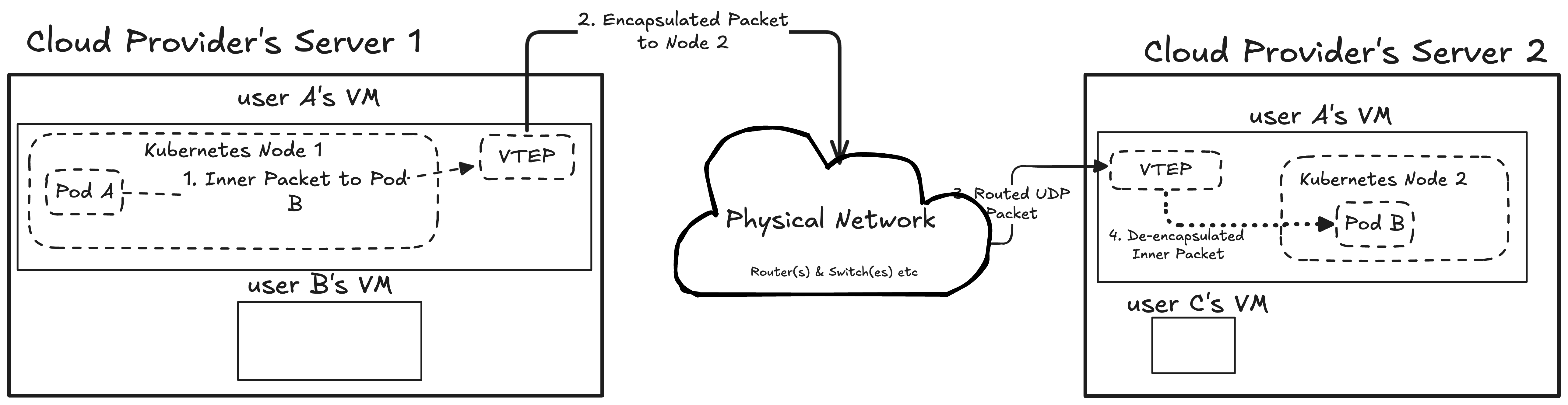
One of the most common overlay networking technique is VXLAN (Virtual Extensible LAN) which uses the similar idea of wrapping packets. Each node has a virtual device called VTEP (Virtual Tunnel Endpoint), where packets are sent to this tunnel endpoint before they are going into other nodes. These VTEP devices are typically created and managed by the CNI daemon (like Flannel’s daemon), which watches the Kubernetes API for new nodes and configures the VXLAN tunnels accordingly.
For example, assume that we have Pod A on Node 1 and Pod B on Node 2. When Pod A on Node 1 sends a packet to Pod B, the packet targets Pod B’s IP address. The kernel recognizes that this Pod is not in our subnet, so the packet is destined to VTEP, because since Pod B’s IP address is local to Node 2, if the physical network receives it, it does not know how to send it to the actual place (similar to NAT problem).
The VTEP encapsulates this packet inside a new UDP packet, which is destined to Node 2’s IP.
+-----------------------------------------------------+
|   Outer IP Header (Source: Node 1, Dest: Node 2)    |
+-----------------------------------------------------+
|   Outer UDP Header (Dest Port: 4789 for VXLAN)      |
+-----------------------------------------------------+
|                 VXLAN Header (VNI)                  |
+-----------------------------------------------------+
|   +---------------------------------------------+   |
|   | Inner IP Header (Source: Pod A, Dest: Pod B)|   |
|   +---------------------------------------------+   |
|   |            Payload (Data)                   |   |
|   +---------------------------------------------+   |
+-----------------------------------------------------+
Note: This is a simplified diagram. A real packet would also include L2 (Ethernet) headers for both the inner and outer packets, as well as a specific VXLAN header. But this illustrates the main idea of wrapping the pod-to-pod packet inside a node-to-node packet.
The physical network sees a normal UDP packet from Node 1 to Node 2 and routes it. Node 2’s kernel receives the UDP packet, sees it’s for VXLAN, and hands it to its VTEP. The VTEP de-encapsulates it, removing the outer UDP packet and what’s left is the original packet addressed to Pod B. Since Node 2 knows that the Pod B is on its system, it delivers it.
This is a popular approach in most cloud providers because it decouples the pod network from the physical network. It allows Kubernetes to create its own flat, virtual network for pods without having to ask the cloud provider to make any special changes to its physical routers. As long as the nodes can send UDP packets (L3 connectivity) to each other, the pod network just works.
Writing CNI Daemon in Go
Finally, in this section, we are going to write a simple daemon utilizing the principles defined in the Routing in Same Subnet section. We’ll create a Kubernetes controller that modifies each node’s route table to ensure networking works as expected.
Our controller will run as a DaemonSet, meaning one copy (one pod) will run on each node in the cluster. This daemon watches for changes to Node objects. Its job is to ensure that the correct routes are set up on the host it’s running on.
It adds a route for every other node in the cluster, telling the host’s kernel: “To reach pods on Node B (with PodCIDR 10.244.1.0/24), send the traffic directly to Node B’s internal IP (e.g., 192.168.1.101).”
How Can a Pod Change the Host’s Routes?
Before we look at the Go code, we should understand how a pod, which is normally an isolated sandbox, is allowed to modify its host. Our DaemonSet’s pod needs several high-privilege settings:
hostNetwork: true: This is the most important setting. It tells Kubernetes to not create a separate network namespace for this pod. The pod will run directly in the host’s network namespace. This gives our controller access to the host’seth0and, crucially, its main routing table.NET_ADMINCapability: Even in the host’s namespace, a process needs permission to change network settings. This capability grants our controller the right to add and delete routes.priorityClassName: system-node-critical: This is a best practice for CNIs. It tells Kubernetes this pod is essential for the node to function, so it should be scheduled first and be the last to get evicted if the node is under resource pressure.tolerations: - operator: Exists: This ensures our DaemonSet pod will run on all nodes, including control-plane nodes that might have taints. This is necessary for full cluster connectivity.
You may also see an initContainer in CNI DaemonSets.
This init container often has privileged: true and mounts hostPath volumes for /opt/cni/bin and /etc/cni/net.d.
Its job is different: it’s responsible for installing the CNI plugin binary (like our bridge plugin) onto the host’s filesystem, so the kubelet can call it.
Controller
Note: The following is a simplified pseudocode representation. It omits error handling, logging, and other production-level details to focus purely on the core logic and execution flow. The source code can be found here for reference: https://github.com/buraksekili/hirs-cni/blob/main/cmd/controllers/node/main.go
| |
Conclusion
We’ve covered a lot of ground in this post. We started with the very basics of networking theory, then saw how those ideas are implemented in Linux with tools like network namespaces, veth pairs, and bridges.
From that foundation, we explored the CNI specification and wrote our own CNI plugin in Go, even tackling tricky concurrency issues like runtime.LockOSThread. We also learned that a plugin is only half the story and went on to build a complete CNI daemon as a Kubernetes controller, teaching it to manage routes across multiple nodes.
While we’ve built a functional CNI, the Kubernetes networking world is vast. We didn’t get to critical features like Network Policy (for security), Service Routing (for ClusterIPs), or IP Address Management (IPAM).
I hope this journey has helped demystify what’s happening under the hood. The next time you deploy a pod and see it instantly get an IP, you’ll know the whole story, from the kubelet calling the plugin for local connectivity, to the CNI daemon ensuring that pod is reachable by the rest of the cluster.
As I mentioned, this is all based on my personal notes. If you find any mistakes or have suggestions, feel free to edit this post through GitHub and raise a PR or contact me via X.
References
- Go Scheduler
- Kubernetes and the CNI: Where We Are and What’s Next - Casey Callendrello, CoreOS
- Linux Namespaces and Go Don’t Mix
- Linux Namespaces Part 4
- Namespaces in operation, part 7: Network namespaces
- Networking and Kubernetes: A Layered Approach
- Runtime Package Documentation
- Tutorial: Communication Is Key - Understanding Kubernetes Networking - Jeff Poole, Vivint Smart Home